The 1 MW solid-state transformer aimed at data centers
NC State, NYPA, and EPRI tested a 1 MW SST on a live feeder. It combines a transformer and rectifier; no customer or data-center deployment has been disclosed.
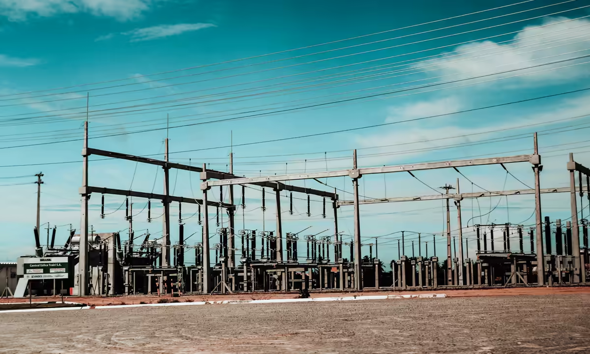
NC State, the New York Power Authority, and EPRI connected a solid-state transformer rated for up to 1 MW to a live distribution feeder at EPRI's power delivery laboratory in Lenox, Massachusetts. Announced on August 18, the supervised test put megawatt-scale hardware on the kind of electrical input that a utility actually operates.¹
Principal investigator Srdjan Lukic called it the first independently verified, megawatt-class solid-state transformer validated on a live utility feeder.¹ That first is the project team's characterization. The published record does not show the prototype powering a data center, running at a customer's site, or entering commercial production.
Data centers enter the story because of the conversion chain the device can replace. The grid supplies medium-voltage alternating current. Servers and other electronics ultimately draw from lower-voltage DC buses. A conventional installation uses a line-frequency transformer to step down the voltage, then a rectifier to convert AC to DC. The prototype folds those functions into one power-electronics system.¹
An EV charger supplied the original design brief
The US Department of Energy funded the underlying hardware under award DE-EE0008450. Its original job was an intelligent, modular extreme-fast-charging station for electric vehicles. Plans called for a direct medium-voltage grid connection, a bidirectional 1 MVA solid-state transformer, a shared DC bus, and solid-state protection for the distribution network behind it.² ³
That history accounts for both the rating and the controls. A high-power charger needs to move a large amount of energy into DC loads without building a separate low-voltage utility entrance around every charging cabinet. The project's final report places the SST between the medium-voltage feeder and a common bus, with local conversion nodes serving individual vehicles.³
A data center could use the same boundary differently: accept medium voltage and produce DC within an integrated front end, removing some intermediate equipment. No integration with an existing facility has been published. Data-center designs also differ in redundancy, backup power, and internal bus voltage.
The ratings describe 1 MW and 1 MVA separately
The 2026 release says the prototype can handle up to 1 MW, a measure of active power. The engineering paper describes a 1 MVA design, an apparent-power rating that also accounts for the relationship between voltage and current.⁴ The numbers can converge at a power factor near one, but they are not interchangeable units.
In the published topology, three-phase 13.2 kV enters a cascaded H-bridge active front end. Isolated dual-active-bridge converters then move energy through high-frequency transformers. Modules are placed in series on the medium-voltage side and paralleled at the output to form a 750 V DC bus.⁴
“Solid state” refers to the semiconductor switches controlling that conversion. Magnetic isolation is still part of the system, operating far above the grid's 50 or 60 Hz frequency. Higher frequency makes smaller magnetic components possible. It also introduces a large population of power switches, gate drivers, sensors, and coordinated control software.
A failed module must be isolated without exposing the DC bus or the 13.2 kV feeder to an uncontrolled fault. The design monitors current and voltage, coordinates converter shutdown, and defines responses for abnormal conditions.⁴ The DOE program had already identified medium-voltage integration, DC protection, and deployment as project barriers.²
The efficiency claim covers the entire AC-to-DC chain
NC State assigns roughly 96% efficiency to a conventional transformer plus rectifier, leaving about 4% of input power as conversion heat. Its release puts the SST at about 98%, or close to 2% loss.¹ The denominator is the complete AC-to-DC path; a standalone passive transformer has a different efficiency curve.
A two-percentage-point difference can matter under a large, sustained load because conversion heat also adds to the facility's cooling burden. NC State also describes the SST as smaller than the conventional pair. The release provides no load-efficiency curve, dimensions, mass, or volumetric power density for the Lenox prototype.¹ Those omissions prevent an independent estimate of the physical or financial advantage for a particular build.
Cost has the same evidence gap. Power electronics combine two pieces of equipment while adding bidirectional flow and active voltage regulation.¹ They also concentrate medium-voltage semiconductors, controls, and specialized fault protection. The public sources include no purchase price, maintenance contract, or service-life comparison with a conventional transformer.
Data centers are the market NC State names
NC State identifies data centers as potential users because they put high power demand and limited space in the same site.¹ Electrical conversion and cooling occupy room that cannot hold compute hardware. An integrated DC bus may also support bidirectional power flow and active voltage regulation when the rest of the facility is designed around those capabilities.
The Lenox test clears one step before procurement: a megawatt-class SST operated on a real feeder under independent EPRI supervision. Longer-duration availability, repair procedures, and field reliability remain unpublished. Utilities and data-center operators would have to qualify insulation, fault response, and coordination with existing protection. Maintenance teams would also be taking responsibility for modular electronics and control software rather than a predominantly passive transformer.
Commercial adoption depends on the space and energy benefits paying for the hardware, qualification work, and lifetime support. The 1 MW prototype leaves that business case open. Its live-feeder demonstration gives a prospective customer a starting point for assessing that case.
Sources
- NC State, New York Power Authority and EPRI Demonstrate Solid State Transformer Success Under Real World Conditions · NC State University · https://research.ncsu.edu/nc-state-new-york-power-authority-and-epri-demonstrate-solid-state-transformer-success-under-real-world-conditions/ · Aug. 18, 2026
- Intelligent, grid-friendly, modular extreme fast charging system with solid-state DC protection · U.S. Department of Energy · https://www.energy.gov/eere/vehicles/articles/intelligent-grid-friendly-modular-extreme-fast-charging-system-solid-state-0 · project DE-EE0008450
Show 2 more sourcesHide sources
- Intelligent, grid-friendly, modular extreme fast charging system with solid-state DC protection · OSTI, final report · https://www.osti.gov/biblio/2371492 · June 10, 2024
- Design, Control, and Protection of a 13.2kV, 1MVA Solid State Transformer for Electric Vehicle Extreme Fast Charging Station · IEEE Transactions on Transportation Electrification / OSTI · https://www.osti.gov/servlets/purl/2561323 · DOI 10.1109/TTE.2024.3462920
— Newsroom